Ford Fusion: Front Seats / Front Seat Backrest Cover. Removal and Installation
Removal
 WARNING:
Front seat backrest trim covers installed on seats equipped
with seat side airbags cannot be repaired. A new trim cover must be
installed. Cleaning is permissible. Failure to follow these instructions
may result in the seat side airbag deploying incorrectly and increase
the risk of serious personal injury or death in a crash.
WARNING:
Front seat backrest trim covers installed on seats equipped
with seat side airbags cannot be repaired. A new trim cover must be
installed. Cleaning is permissible. Failure to follow these instructions
may result in the seat side airbag deploying incorrectly and increase
the risk of serious personal injury or death in a crash.
NOTE: LH seat shown, RH seat similar.
NOTE: Removal steps in this procedure may contain installation details.
-
Remove the front seat.
Refer to: Front Seat (501-10A Front Seats, Removal and Installation).
-
Remove the front head restraint guide sleeve.
Refer to: Front Head Restraint Guide Sleeve (501-10 Front Seats) .
-
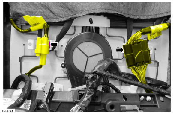
Detach the electrical connector retainers and position the wire harnesses aside.
 |
-
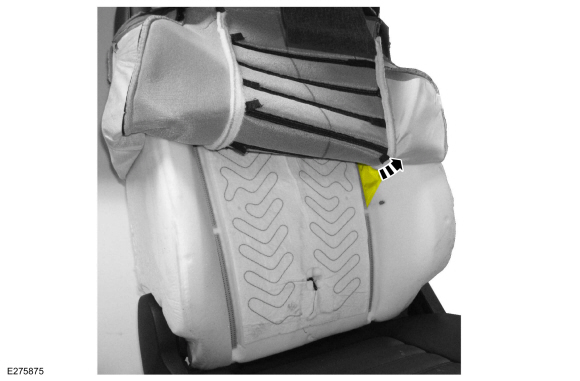
Detach the backrest cover straps and position the backrest cover upward.
 |
-
-
Remove the pin-type retainers.
-
Detach the hook-and-loop strips.
-
Lift the backrest cover flap.
-
Remove the pin-type retainers.
 |
-
Position the front seat backrest cover.
-
Release the J-clip.
-
Position the backrest cover from between the seat cushion and backrest cushion.
-
Release the J-clip.
 |
-
Remove the backrest cover insert.
 |
-
NOTICE: Use care when separating the backrest trim cover from the hook-and-loop strips or the hook-and-loop strips may be torn from the backrest foam.
Partially invert the backrest cover enough to access the hog rings.
-
Release the hook-and-loop strips.
-
Invert the backrest cover.
-
Release the hook-and-loop strips.
 |
-
Remove the pin-type retainers from the deployment chute wrap and begin feeding it through the backrest foam.
 |
-
Pull the deployment chute wrap out of the backrest foam.
 |
-
Lift the backrest cover and release the J-clips from the lumbar wires and backrest frame.
 |
-
NOTICE: Use care when separating the backrest trim cover from the hook-and-loop strips or the hook-and-loop strips may be torn from the backrest foam.
Remove the hog rings, detach the hook-and-loop strips and remove the backrest cover.
 |
Installation
-
To install, reverse the removal procedure.
 Front Seat Backrest Blower Motor. Removal and Installation
Removal
Remove the front seat.
Refer to: Front Seat (501-10A Front Seats, Removal and Installation).
Detach the electrical connector retainers and position the wire harnesses aside...
 Front Seat Control Switch. Removal and Installation
Removal
Remove the side shield screws.
Remove the side shield.
Lift up on the rear of the side shield and pull outward...
Other information:
Ford Fusion 2013–2020 Service Manual: Rear Seat Backrest. Removal and Installation
Removal NOTE: Removal steps in this procedure may contain installation details. NOTE: The 40 percent backrest must be removed to allow removal of the 60 percent backrest. All backrests Remove the rear LH seatbelt buckle. Refer to: Rear Seatbelt Buckle LH (501-20A Seatbelt Systems, Removal and Installation)...
Ford Fusion 2013–2020 Service Manual: Communications Network - System Operation and Component Description. Description and Operation
System Operation System Diagram Item Description 1 BCM 2 DDM 3 PDM 4 DSP 5 ACM 6 PSCM 7 GPSM 8 IPMA 9 OCSM 10 RCM 11 PCM 12 GWM 13 FCDIM 14 DLC 15 SODL 16 SODR 17 DSM 18 HUD 19 RTM 20 ..
Categories
- Manuals Home
- 2nd Generation Ford Fusion Owners Manual
- 2nd Generation Ford Fusion Service Manual
- Transmission - 1.5L EcoBoost (118kW/160PS) – I4. Removal and Installation
- Body Control Module (BCM). Removal and Installation
- Automatic Transmission Fluid Check - 1.5L EcoBoost™/2.0L EcoBoost™/2.5L. Automatic Transmission Fluid Check - 2.7L EcoBoost™
- New on site
- Most important about car
Understanding Your Tire Pressure Monitoring System

The tire pressure monitoring system measures pressure in your road tires and sends the tire pressure readings to your vehicle. You can view the tire pressure readings through the information display. The low tire pressure warning light will turn on if the tire pressure is significantly low. Once the light is illuminated, your tires are under-inflated and need to be inflated to the manufacturer’s recommended tire pressure. Even if the light turns on and a short time later turns off, your tire pressure still needs to be checked.