Ford Fusion: Engine - 1.5L EcoBoost (118kW/160PS) – I4 / Engine. Removal
Special Tool(s) /
General Equipment
 |
300-OTC1585AE
Powertrain Lift |
 |
300-OTC1819E
2,200# Floor Crane, Fold Away |
 |
303-1502
Lifting Device Engine
TKIT-2012A-FL
TKIT-2012A-ROW |
 |
307-569
Disconnect Tool TOC Line (1/2)
TKIT-2006U-F/FM
TKIT-2006U-FLM/LM
TKIT-2006U-ROW1
TKIT-2006U-ROW2 |
| Strap Wrench |
| Adjustable Mounting Arm |
| Oil Drain Equipment |
| Hose Clamp Remover/Installer |
| Wooden Block |
All vehicles
-
With the vehicle in NEUTRAL, position it on a hoist.
Refer to: Jacking and Lifting - Overview (100-02 Jacking and Lifting, Description and Operation).
-
Release the fuel system pressure.
Refer to: Fuel System Pressure Release (310-00A Fuel System - General Information - 1.5L EcoBoost (118kW/160PS) – I4, General Procedures).
-
Keep the steering wheel in the straight-ahead position.
-
Remove and discard the bolt. Detach the steering column shaft from steering input shaft.
Torque:
18 lb.ft (25 Nm)
-
Remove the engine appearance cover.
-
Recover the A/C system.
Refer to: Air Conditioning (A/C) System Recovery, Evacuation and Charging - Vehicles With: R1234YF Refrigerant (412-00 Climate Control System - General Information, General Procedures).
-
Drain the cooling system.
Refer to: Engine Cooling System Draining, Vacuum Filling and Bleeding (303-03A Engine Cooling - 1.5L EcoBoost (118kW/160PS) – I4, General Procedures).
-
Remove the following items:
-
Remove the air cleaner.
Refer to: Air Cleaner (303-12A Intake Air Distribution and Filtering - 1.5L EcoBoost (118kW/160PS) – I4, Removal and Installation).
-
Remove the upper air cleaner outlet pipe.
Refer to: Air Cleaner Outlet Pipe (303-12A Intake Air Distribution and Filtering - 1.5L EcoBoost (118kW/160PS) – I4, Removal and Installation).
-
Remove the battery tray.
Refer to: Battery Tray (414-01 Battery, Mounting and Cables, Removal and Installation).
-
NOTE:
Always wrap the fuel line connection with a towel before disconnecting it.
Detach the retainers, disconnect the couplings and position the fuel tube aside.
-
Detach the retainer and disconnect the coupling and position the vacuum tube aside.
-
Disconnect the crankcase pressure sensor wiring harness electrical connector and wire harness retainer.
-
Remove the EVAP canister purge valve.
Refer to: Evaporative Emission Canister Purge Valve (303-13A Evaporative Emissions - 1.5L EcoBoost (118kW/160PS) – I4, Removal and Installation).
-
Remove the stud bolt and position the wiring harness aside.
-
Release the tabs and position the fuse box aside.
-
Release the tabs and open the battery cable terminal cover.
-
Remove the nuts and position the wiring harness aside.
-
Detach the retainers, remove the bolts and position the wiring harness aside.
-
Disconnect the coolant hose.
Use the General Equipment: Hose Clamp Remover/Installer
-
Remove the transmission fluid cooler tubes secondary latches.
-
Using the special tool, disconnect the transmission fluid cooler tubes.
Use Special Service Tool: 307-569
Disconnect Tool TOC Line (1/2).
-
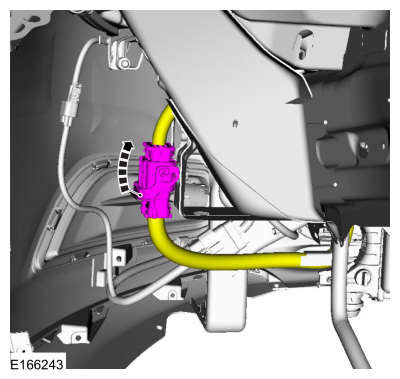
Detach the retainer and disconnect the coolant tube.
Use the General Equipment: Hose Clamp Remover/Installer
-
NOTE:
If equipped with block heater.
Detach the retainers and disconnect the coolant tube.
-
Remove the bolts and disconnect the gearshift cable end from selector lever assembly.
-
NOTE:
Note the position of the coolant hoses for installation.
Disconnect the coolant hoses from the heater core.
Use the General Equipment: Hose Clamp Remover/Installer
-
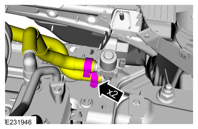
Release the clamps and disconnect the coolant hoses from the transmission fluid heater coolant control valve.
Use the General Equipment: Hose Clamp Remover/Installer
-
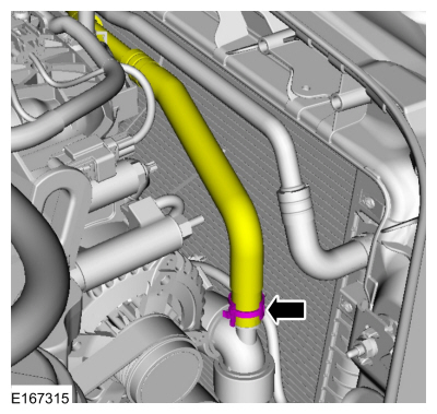
Disconnect the coolant hose.
Use the General Equipment: Hose Clamp Remover/Installer
-
Disconnect the PCM electrical connector.
-
Detach the wiring harness retainer, disconnect the electrical connector and position the wiring harness aside.
-
-
Disconnect the coolant hoses.
Use the General Equipment: Hose Clamp Remover/Installer
-
Release the tab, remove the retainer and the degas bottle.
-
Support the cooling module.
-
Remove the accessory drive belt.
Refer to: Accessory Drive Belt (303-05A Accessory Drive - 1.5L EcoBoost (118kW/160PS) – I4, Removal and Installation).
-
Remove the RH and LH front wheels and tires.
Refer to: Wheel and Tire (204-04A Wheels and Tires, Removal and Installation).
-
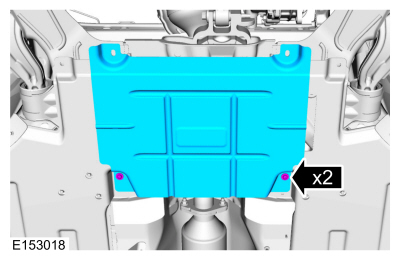
Remove the retainers and the stone guard.
-
Remove the retainers and the deflector shields.
-
NOTE:
LH inner fender well removed for clarity.
Disconnect the electrical connector.
-
Remove the retainers and the lower radiator support.
-
Disconnect the coolant hoses and detach the retainers.
Use the General Equipment: Hose Clamp Remover/Installer
-
Disconnect the coolant hose.
Use the General Equipment: Hose Clamp Remover/Installer
-
Disconnect the electrical connectors, detach the retainers and position wiring harness aside.
-
NOTE:
Discard the O-ring seals and gasket seals.
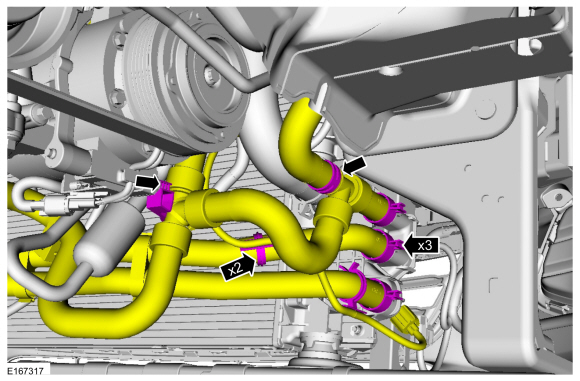
Remove the nuts and position the A/C lines aside.
-
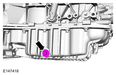
Remove the drain plug, drain engine oil and install drain plug.
Use the General Equipment: Oil Drain Equipment
Torque:
21 lb.ft (28 Nm)
-
Remove and discard the engine oil filter.
Use the General Equipment: Strap Wrench
-
Remove the bolts and the cross support.
-
Remove the nuts and position the muffler inlet pipe aside. Discard the nuts.
-
Remove and discard the muffler inlet pipe gasket.
-
Mark on subframe before removal.
-
Mark on subframe before removal.
-
Remove the bolts and position the auxiliary water pump aside.
-
NOTE:
One of these bolts will be used to mount the Adjustable Mounting Arm to the powertrain.
Remove the engine to transmission bolts.
-
Remove the nuts and the catalytic converter grommet.
-
Remove the bolt position the wheel speed sensor aside.
-
Remove the bolt position the wheel speed sensor aside.
-
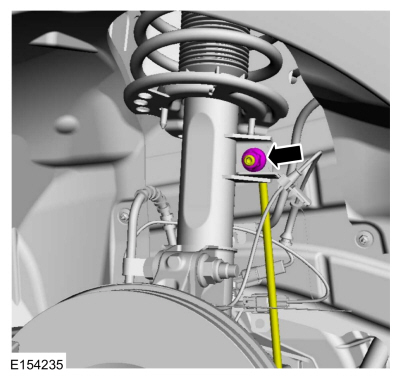
Remove the nut and position the LH stabilizer bar link aside.
-
Remove the nut and position the RH stabilizer bar link aside.
-
Position a 2 x 8 board, 40 in (1016 mm) in length, a 2 x
6 board 28 in (711.2 mm) in length, a 1 x 6 board 28 in (711.2 mm) in
length and two 2 x 4 boards 12 in (304.8 mm) in length onto the
Powertrain Lift 300-OTC1585AE.
Install Special Service Tool: 300-OTC1585AE
Powertrain Lift.
Use the General Equipment: Wooden Block
-
Install Special Service Tool: 300-OTC1585AE
Powertrain Lift.
Use the General Equipment: Wooden Block
-
Install the adjustable mounting arm.
Use the General Equipment: Adjustable Mounting Arm
-
Remove the brake disc.
Refer to: Brake Disc (206-03 Front Disc Brake, Removal and Installation).
-
Remove the nuts, bolts and the position the LH wheel knuckle assembly aside.
-
Remove the nuts, bolts and the position the RH wheel knuckle assembly aside.
-
Remove the transmission support insulator nut.
-
-
Remove the nuts, bolts and the engine mount.
-
Discard the nuts and bolts.
-
-
Remove and discard the subframe rear mounting bolts.
-
Remove the bolts and the subframe support bracket.
-
Remove and discard the subframe front mounting bolts.
-
Using the powertrain lift, lower the powertrain and subframe as an assembly.
-
Detach the retainer and disconnect the electrical connectors.
-
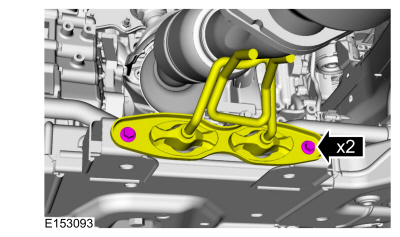
Remove the muffler inlet pipe isolator bracket bolts.
-
Remove and discard the catalytic converter bolt.
-
Remove the bolts and the catalytic converter. Discard the bolts.
-
Remove and discard the catalytic converter gasket.
-
Detach the wiring harness retainers and disconnect the electrical connectors.
Vehicles with automatic start-stop
-
Disconnect the coolant hoses.
Use the General Equipment: Hose Clamp Remover/Installer
All vehicles
-
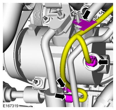
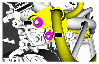
Remove the nuts and position the starter motor cable aside.
-
-
Detach the wiring harness retainers, disconnect the electrical connector.
-
Slide the generator insulator up, remove the nut and position the wiring harness aside.
-
Remove the nut and position the wiring harness aside.
-
Remove the bolts, stud bolt and the starter motor.
-
Remove the starter motor insulator.
-
NOTE:
Only rotate the crankshaft in a clockwise direction.
Index-mark the torque converter nuts. Remove and discard the torque converter nuts.
-
-
Detach the wiring harness retainer.
-
Disconnect and remove the crankcase vent hose.
Use the General Equipment: Hose Clamp Remover/Installer
-
-
Detach the wiring harness retainers and disconnect the electrical connectors.
-
Disconnect the TC bypass hose.
-
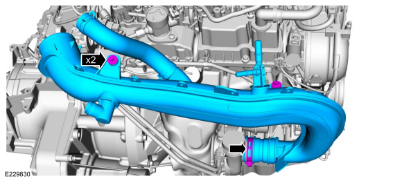
Loosen the clamp, remove the bolt and the TC outlet pipe.
-
Loosen the clamp, remove the bolts and the TC inlet pipe.
-
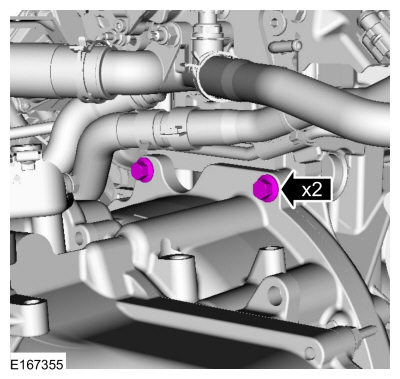
Remove the bolts and position the halfshaft support bracket aside.
-
Remove the bolts and the bracket.
-
Install Special Service Tool: 303-1502
Lifting Device Engine.
-
Install Special Service Tool: 300-OTC1819E
2,200# Floor Crane, Fold Away.
-
Remove the bolts and the adjustable mounting arm.
Use the General Equipment: Adjustable Mounting Arm
-
Remove the engine to transmission bolts.
-
Remove the engine to transmission bolts.
-
Remove the bolt and separate the engine from transmission.
Special Tool(s) /
General Equipment
100-001
(T50T-100-A)
Slide Hammer
300-OTC1819E2,200# Floor Crane, Fold Away
303-1097Locking Tool, Variable Camshaft Timing Oil Control UnitTKIT-2010B-FLMTKIT-2010B-ROW
303-1502Lifting Device EngineTKIT-2012A-FLTKIT-2012A-ROW
303-409
(T92C-6700-CH)
Remover, Crankshaft SealTKIT-1992-FH/FMH/FLMHTKIT-1993-LMH/MH
303-748L..
Other information:
Removal
NOTE:
Removal steps in this procedure may contain installation details.
NOTICE:
Do not service the brake pedal or brake booster
without first removing the stoplamp switch. This switch must be removed
with the brake pedal in the at-rest position. The switch plunger must be
compressed for the switch to rotate in the bracket. Attempting to
remove the switch when the plunger ..
Removal
NOTE:
Removal steps in this procedure may contain installation details.
NOTE:
RH seat shown, LH seat similar.
Remove the screw.
Torque:
8 lb.in (0.9 Nm)
Disconnect the electrical connector.
Remove the seat position sensor.
Installation
To install, reverse the removal procedure.
..




















 Engine. Disassembly

